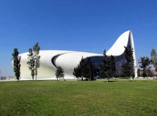
Centro Cultural Heydar Aliyev/Heydar Aliyev Cultural Center. Arquiteta/Architect Zaha Hadid
Florian Gauss, 2015
Maycon Sedrez: Can you tell me about the digital fabrications techniques that you worked with? For instance in the case of the Egyptian Museum, how is going to be produced the parts?
Florian Gauss: That is not built yet. I haven’t been involved in that. I was hoping to get involved because is going to get a German contractor and we also made an offer to them. But I can show another example of fabrication which is a nice one. This is Cultural Center in Baku from Zaha Hadid. The surface is about 35.000 square meters of GRC (3) or GRP (4) panel or individuals shaped curves and so on. And for that I developed the substructure which is holding up all the panels. I can also tell you how the panels were produced and rationalized.
MS: Yes. I would like to know.
FG: There was a system which relied on the space frame, which is the main structural build up. It is a Mero system (5), and we had at three meters centers always a rod sticking through the insulation and water-proofing layer, this element. Where then you can connect with the substructure which is holding up the façade. Here you can see, this is the Mero and the ball and then you have the rod sticking trough and of course is going to be sealed and water-proof and so on.
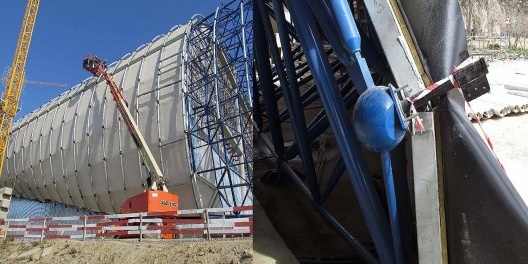
Subestrutura e o detalhe da haste/Substructure and the rod detail
Florian Gauss, 2015
Therefore there was a detail developed which fits each and every node. So the detail of the node is always the same. Of course the geometry is different. You can see these tubes are more or less offsetting the surface of the inner envelope and approximating the outside envelope. And it was build out of twenty individual arc sections, arcs. As you see in the color coding, each different color has a different arc diameter.
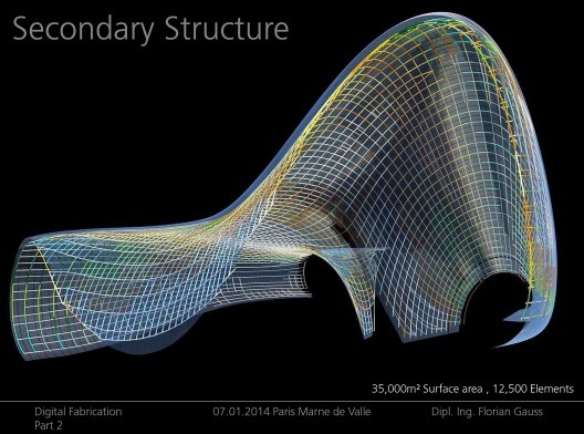
Estrutura secundária/Secondary structure
Florian Gauss, 2015
So it was done in a way that you have always 20mm steps between the arcs of the curvature. We take the base length of the three meters, some of them are flat, the white ones are flat, and they are straight. Then you go up always in steps of 20mm, which we said that is the tolerance, until we reach the maximum curvature which is in the building and therefore we have twenty different arcs which are covering the whole curvature scenario of the surface.
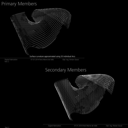
Membros primários e secundários/Primary and Secondary members
Florian Gauss, 2015
MS: Is this the rationalization of the façade? Did you think of how much material are you going to use to produce this?
FG: No. The surface was not rationalized. The surface was giving. It was not optimized. It was set by the architects; also the seams of the panels were given. Purely from aesthetic and architectural reason, there is no rationalization or fabrication issue behind it. It was just set; they said that is how we want to have it.
So the whole thing is based on the space frame with nodes at the three meters roughly which gives you a cloud of fixing points, and in between the fixing points we had this detail. The detail in one end was fixed in one direction but you can swing it around the axis of this rod. An in the other end is always a system, which you can see the front end and the back end, this one is a pin which is going into there, so you can also rotate it and swing it. So you can adjust your arc into any position you want to like. Then the algorithm always takes out of the series of arcs which we defined, takes the most suitable one and puts on the roof.
Then you go along with the seams which were given by the architects. And off course along the seams you have to connect, you have to also to provide secondary arcs, a secondary structure. This principle is exactly the same, however you can see because the fiber plastic panels need supports and certain distant. So maximum span was one and a half meter but all the panels have a different length. So it also automatically picks how much intermediate supports you would need. Here you can see an overlay, this is the direction of the space frame which is underline and then in the crossing direction you have the secondary beams which are following the seams and also the intermediate support points of the panels. Now that we set of this data we extracted the fabrication information, so you have the arc number, the length of the arc, the radius of the arc, also the point where you have to fix, for example, secondary elements and the fixings of the panel. So it was only given as the distance from the start to the end. This is kind of a typical drawing; all the parts are the same the only thing that is changing is the geometry, the length and the bending radius of the arc. Also you have to mark from which distance from the start you have to drill a hole to fix a panel fixing or a secondary member for example, so it was parametrized in a very simple term without too much BIM technology. It was really a very pragmatic concept of how you are going to set up your secondary structure system; you can really condense your fabrication information to a set of typical drawings and spread sheets.
That is the panel fabrication, we didn’t work on it, it was another company. They took all the panels of the roof and roll them flat as far as possible and then they gave them literally the edge curves of the panel which was cut out of plywood for a template. They had a flexible plywood as a shutter. Initially the fabricator idea was to use an adjustable rig, so you have pins and balls which can screw up and down. And the design company already produced all the data for it, all the height level, so he had to screw up the pins. However they found out the process of doing it with timber mold, cut out of timber, and just hire a more cheap labor was easier and cheaper than this adjustable shutter. He did it just with a lot of people from India or Sri Lanka, because it was produced in Dubai.
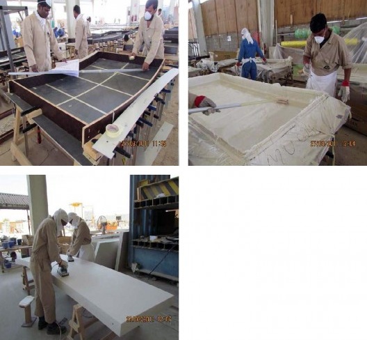
Fabricação dos painéis/Fabrication of the panels
Florian Gauss, 2015
Of course, the substructure of the edges where pure hand work, because there was no rule given, there was no rule applicable to create the curve. Somebody just modelled all the substructure beams by hand for an half of year, because there was no way to get it done parametrically or with a programming approach. You only have exceptions, only a human can judge what we are going to do here in the center. Therefore always the edges are where the most work sits in.
MS: I would like to know about costs. In terms of costs, what makes a complex design costs more then, let’s say, a more regular design? For instance in this Zaha Hadid building, did it cost more because of the hand designed beams?
FG: Of course is the fabrication; because you have to fabricate individual parts which first might be an expensive way of fabricating it. For example, glass, by default you are going to fabricate plain glass. If you want curved glass… if it is a single curved glass you have to bend it so it is an additional step of fabrication which costs you money. If it is double curved it is four times the price because you have to build an individual mold for it. It is about the fabrication steps to get the end product. The less fabrication steps you have, the less are the costs. The more you have to do get the shapes, the higher are the costs. If you just take a tube and cut it is cheap, if you have to bend it a single way it adds costs, but maybe it is ok. But then if you have to introduce a helicoid bending it is more complex and costly way of fabricating it. Therefore you have more costs, and of course there are logistics and tolerances, if you have a higher developed fabrication then the tolerances are maybe higher, so you have fall out parts which you just cannot use. For example, if you bend glass, double curvature, you are going to destroy a few examples while you are doing it and that also has to be paid. For example the GRC panels, for each individual panel you have to produce a mold, it is a lot of cost. If you have a flat mold which has always the same parts, then you are going to do it in steel and you can use it a hundred thousand times.
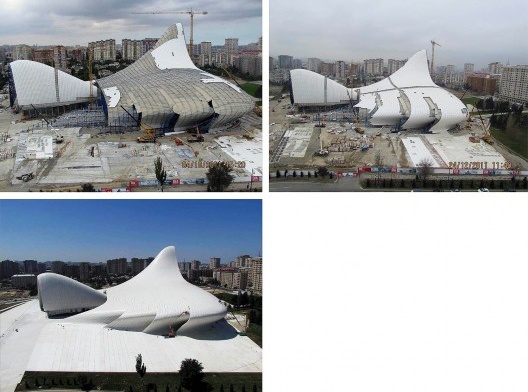
Instalação dos painéis/Panels installation
Florian Gauss, 2015
notes
3
GRC – Glass Reinforced Concrete.
4
GRP – Glass Reinforced Polyester.
5
Mero Structures, website official <www.mero-structures.com>.


